Asynchronous Serial Protocol (UART)
UARTUniversal Asynchronous Receiver/Transmitter is an alternative to SPISerial Peripheral Interface. The module can be configured to use UART to communicate. For some MCUs, UART is more convenient.
By default, UART operates at 115,200 bits/sec (the module can be configured with different speeds). UART uses 8-bit characters, odd parity, and 1 stop bit.
The interface requires hardware flow control. Each side uses flow-control signals to send messages.
The serial protocol has framed and encapsulated packets similar to SPI protocol packets.
Following are descriptions of the framing, encapsulation, packet types, and error handling for UART; click each to display the information:
Each packet is framed using a scheme similar to that used by PPPPoint-Point Protocol, as described in RFC-1622 section 4. Ayla does not use the address and control bytes that PPP defines, however. It isn’t necessary to be familiar with that RFC or PPP to understand the framing.
Each frame, in both directions, begins and ends with a flag byte (0x7e).
Any flag byte occurrence in a packet is replaced by the two-byte sequence 0x7d 0x5e. 0x7d is the escape byte. Any 0x7d in packet is replaced by 0x7d 0x5d. The second byte of this escape sequence is the original byte XORed with 0x20.
Only one flag byte is necessary between frames (sometimes a flag byte is sent at the frame beginning, if not sent in a while). Two flag bytes in a row imply an empty frame (to be discarded).
Each packet is encapsulated with a packet type with a sequence number before the packet and a CRCCyclic Redundancy Check-16 code after the packet. Then, the packet is framed. Following illustrates the protocol hierarchy for UART:
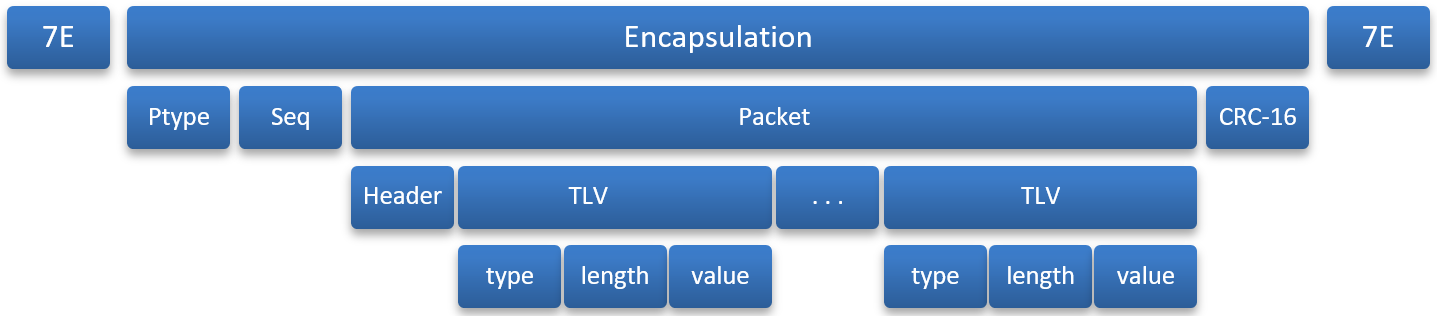
The encapsulation between flag bytes is shown in the following table:
| Bytes | Name | Meaning |
| 0 | Ptype |
Packet type code |
| 1 | Seq | Sequence number |
| 2 to N+1 | Payload | Data or Control packet |
| N+2 to N+3 | CRC-6 | Redundancy check over payload, MSBmost significant bit first |
The packet (header and TLVstype / length / value items) are same as in SPISerial Peripheral Interface protocol.
CRC-16 is computed over all bytes after the flag byte, before byte-stuffing for transmit. This is done with a CRC-generator using the CCITTConsultative Committee for International Telephone and Telegraph polynomial. It is initialized to 0xffff and computed with the payload’s MSB. CRC is placed in network byte order after the payload. A CRC payload check and the transmitted CRC results in a return value of 0.
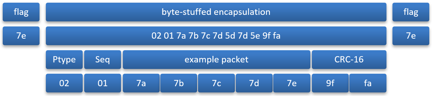
To prepare a packet for transmission, the following process takes place:
- Start with the payload to be sent (for example, 7a 7b 7c 7d 7e).
- Prepend the ptype (e.g., 0x02) and sequence number (e.g., 0x01).
- Compute CRC-16 over the ptype, sequence number and payload and append it. (CRC in this case would be 0x9ffa).
At this point, the frame is: 02 01 7a 7b 7c 7d 7e 9f fa. (5 bytes plus 4 bytes of overhead).
- Perform octet stuffing and add flag bytes.
At this point, the frame is: 7e 02 01 7a 7b 7c 7d 5d 7d 5e 12 34 7e. These 13 bytes are sent. 5 (data) + 4 (length and CRC) + 2 (byte stuffing) + 2 (flag bytes) = 13.
Following is an example packet:
The table below lists the currently-defined packet types. All other packet types are reserved and should be ignored if received by the MCU.
| Ptype | Name | Meaning |
| 0x01 | Data |
The packet is a data, control, or ping packet. |
| 0x02 | ACKAcknowledgement | Acknowledges packet receipt as indicated by the sequence ID. |
Errors detectable on the serial protocol include CRC mismatch, invalid frames, invalid Ptype, overruns, and parity errors. These should be counted, but otherwise ignored.
A missing ACK (timeout) causes retransmission (at least the first two times it happens) on a given sequence ID. The module drops packets after two retries. The MCU may reset the module after too many retries, or take other appropriate action. The sender should ensure that the packet was transmitted and not just unable to be sent due to flow-control.
A packet received with the same sequence number as the previous packet (but not zero) should generate an ACK, but otherwise be dropped. This is how lost ACKs are handled.
The special sequence number zero indicates that the sender has restarted. Both the MCU and the module start with a zero-sequence number (after starting, zero is never reused) - called a "lollipop" sequence number scheme.
Please click here to let us know how we're doing. Thank you.