Ayla Module and the MCU Interface
The Microcontroller Unit (MCU) connects to the Ayla Module using SPI (serial peripheral interface) or UART (universal asynchronous receiver/transmitter). Following provides overviews on the properties, datapoints, and protocols involved in the connection process.
Properties and Datapoints
The Ayla Module sends and receives name/value pairs between the MCU and the Ayla Device Service (ADS). Names are called properties. Values are called datapoints.
A property and its datapoints can represent anything that the MCU defines. The property may represent the state of a light or switch, a temperature sensor reading, the desired thermostat temperature, a moisture sensor, a schedule for a sprinkler system, an input to a calculation, or just about anything.
Property names are ASCII strings (up to 27 characters):
- Upper and lower-case letters
- Numbers
- Hyphens (-)
- Underscores (_)
- Spaces or special characters are not allowed.
- First character must be alphabetic.
Properties have a value data type, such as integer, Boolean, string (UTF-8), or binary. Property datapoints are values associated with the property (usually the most recent datapoint).
Most of these documented capabilities are for module configuration and are optional. The MCU may also perform module configuration during datapoints have values are less than 255 bytes (maximum that can be passed in a single message). A datapoint can be up to 4 GB long.
Protocols
A host MCU connects to an Ayla Module with SPI or UART. The interface is designed to work with variety of MCU sizes. Some modules may support only one of these modes. Most of the documented capabilities are for module configuration and are optional. The MCU may also perform module configuration during manufacturing.
Whether SPI or UART is used for communications, the three levels of protocols are:
- Single-byte simple commands to get status or start a transfer.
- Packet transfer command sequences.
- Data or control protocol packets with a header and optional TLVs (type / length / value items)
The following diagram of the protocal hierarchy for SPI shows phases of a packet transfer sequence.
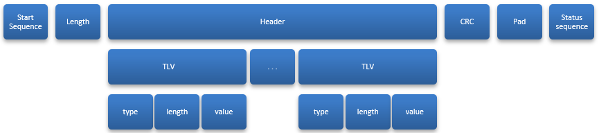
The first row shows the sequence. The Start sequence, pad, and status sequence are different for SPI and serial, but Length, Packet and CRC (cyclic redundancy check) are similar. Every packet transfer includes:
- Start sequence (single-byte commands and status exchanges)
- Length field
- Packet being sent
- Cyclic redundancy check (CRC)
|
NOTE |
Padding bytes may be required before the status sequence is performed. |
The first row also shows the packet and its encapsulation. The second row shows the header and TLVs forming the packet. The third row shows TLV contents (type, length, value).
Please click here to let us know how we're doing. Thank you.